FACILITY
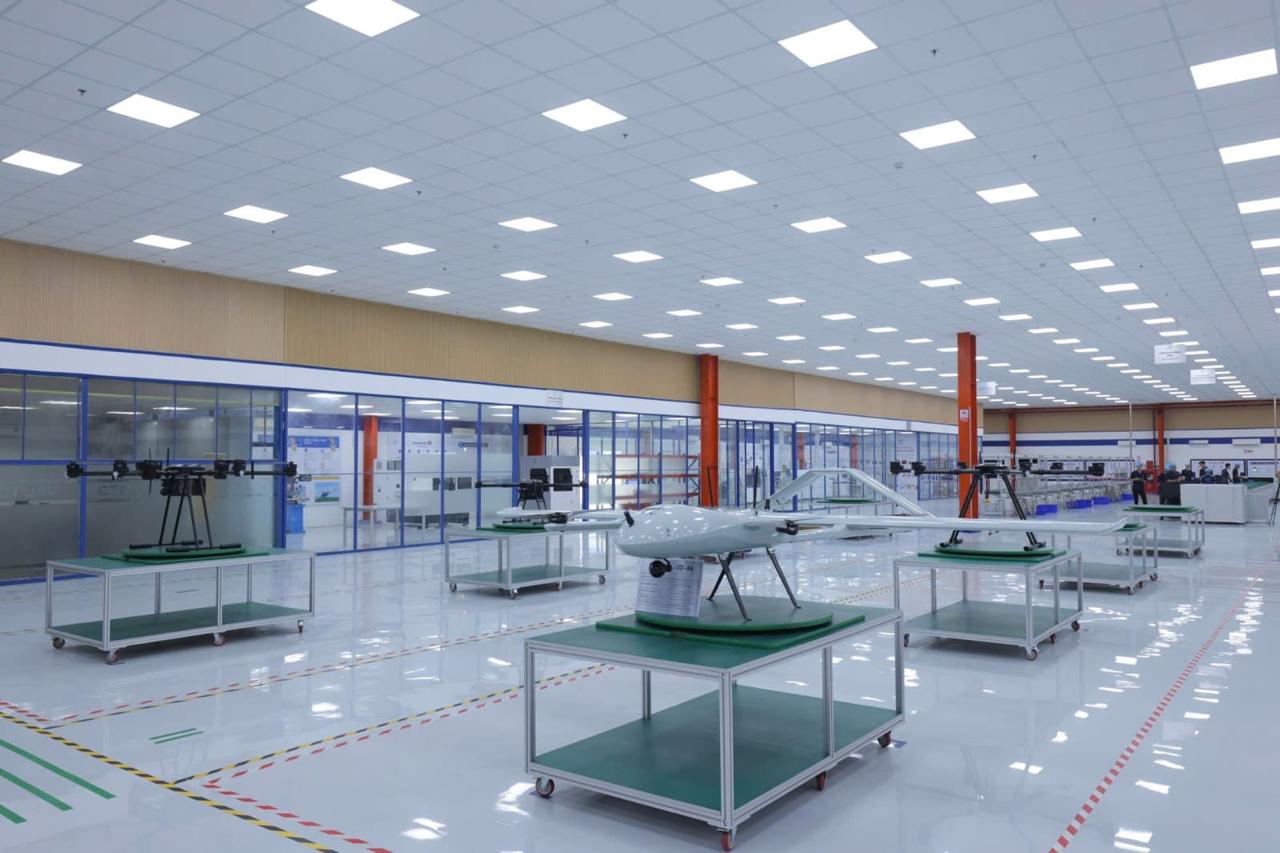
A defined environment for each process.
Production instructions, materials and work areas are prepared before fabrication begins.
LOADING THE JOURNEY
CT UAV MANUFACTURING
See how CT UAV connects engineering, component production, system integration and verification in one manufacturing process.
Each build moves through defined design, material, assembly and verification steps. Records at every stage support consistency and traceability.
Convert operating requirements into a controlled design.
Produce parts to documented dimensions and processes.
Combine the airframe, electronics, propulsion, software and payload.
Inspect and review the build before release.
Use test and field feedback in the next design cycle.
FACILITY
Production instructions, materials and work areas are prepared before fabrication begins.
PRECISION MACHINING
Machining controls the interfaces that affect fit, alignment and later assembly.
ELECTRONICS
Electronic assemblies are prepared and inspected before installation in the aircraft.
AUTOMATION
Automated equipment handles repeatable steps while technicians monitor the process.
SYSTEM INTEGRATION
Structure, electronics, propulsion, software and payload are integrated before system-level verification.
Loading the production sequence
The interactive model shows how the main engineering areas connect within an aircraft.
Drag to inspect · Select an area
Material selection, structural design, tooling and fabrication are balanced for weight, strength, durability and production.
Propulsion and power components are arranged for balance, cooling, access and maintenance.
Flight computers, control software and configurations are integrated and reviewed before system testing.
Antennas, radios and data paths are positioned to support aircraft control and mission data transfer.
Payload mounting, power, data and field configuration are considered as part of the aircraft design.
Onboard electronics connect sensing, control and data processing with traceable production records.
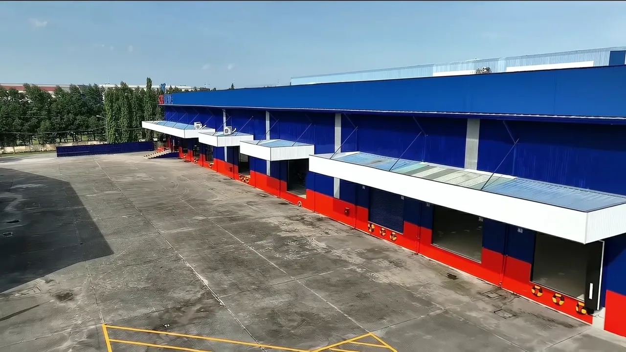
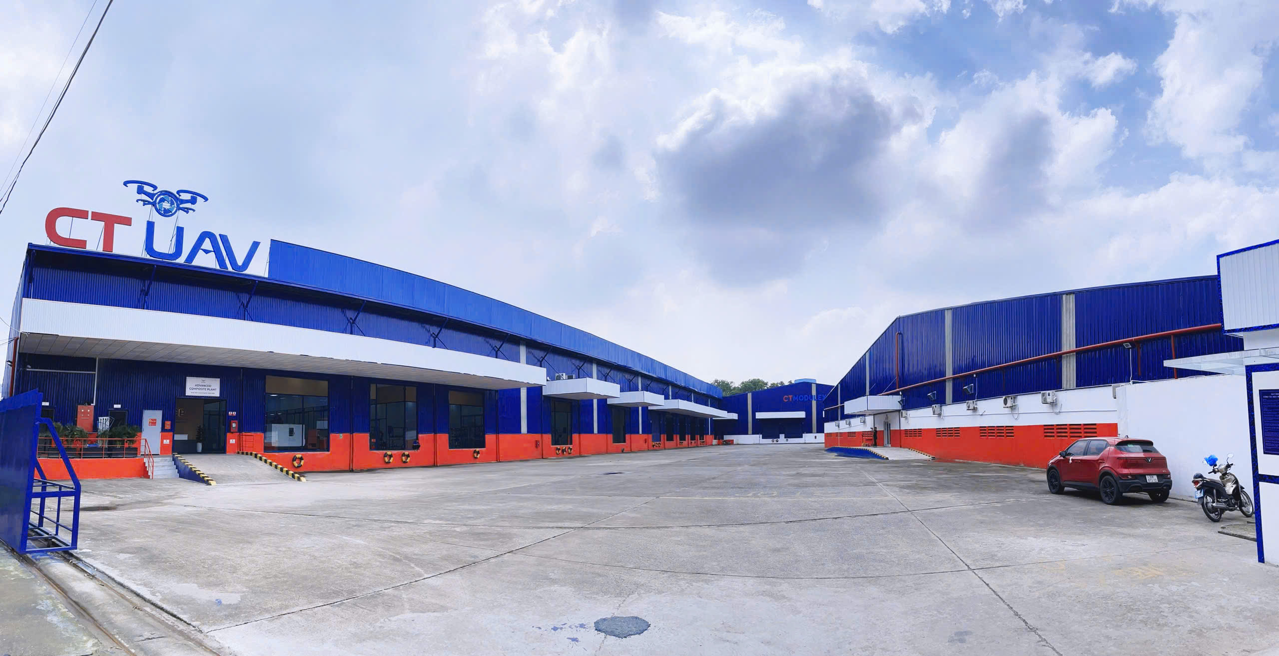
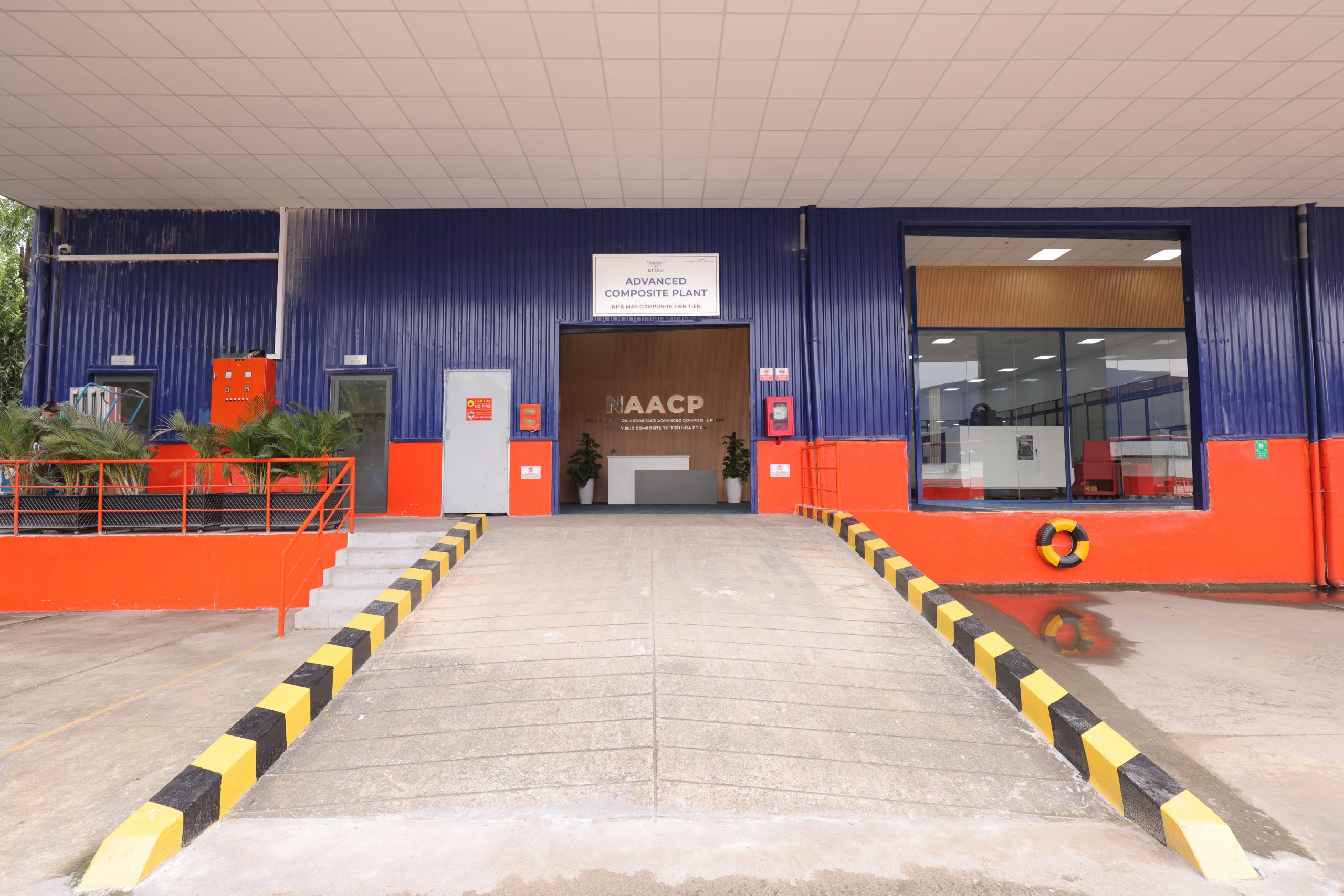
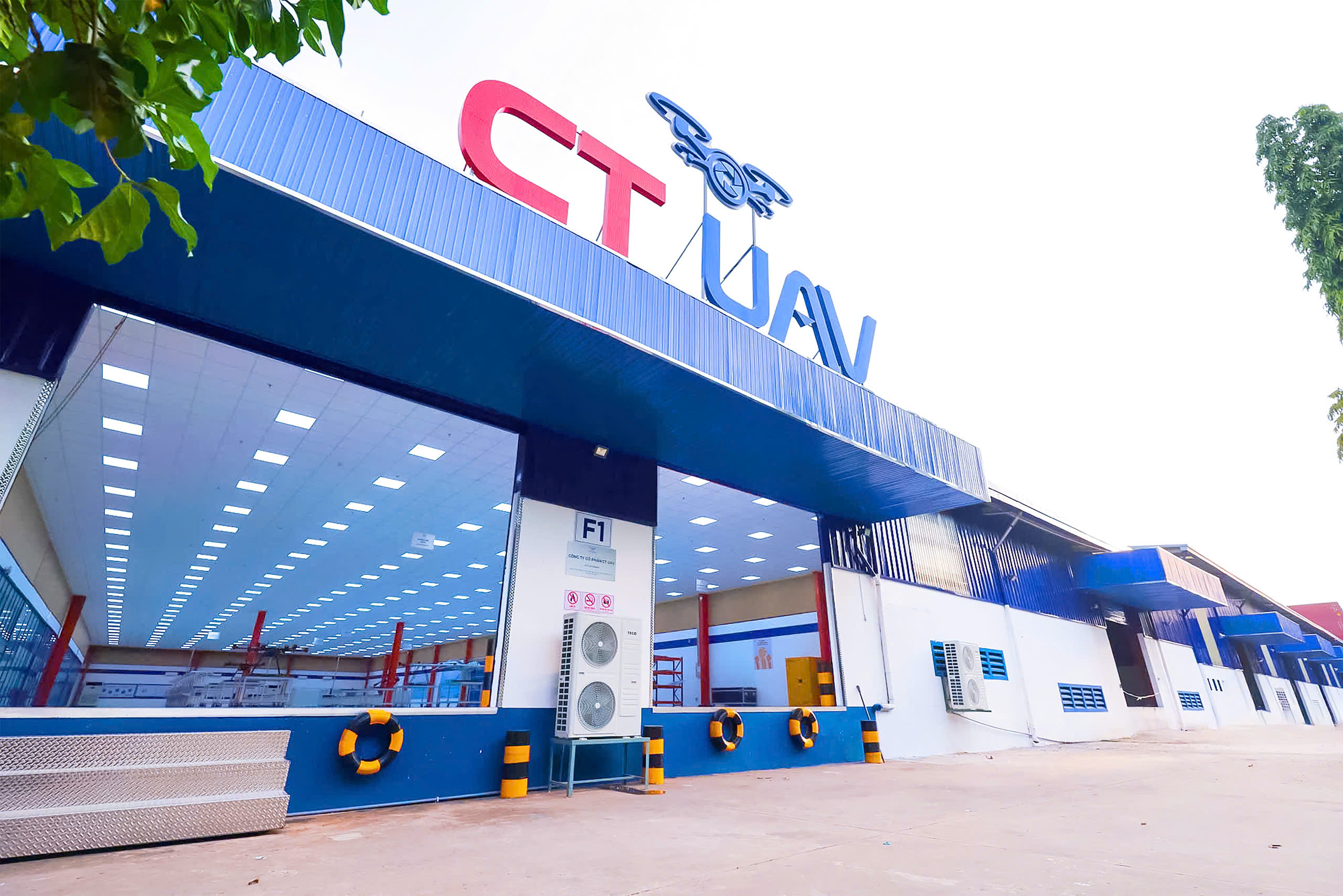
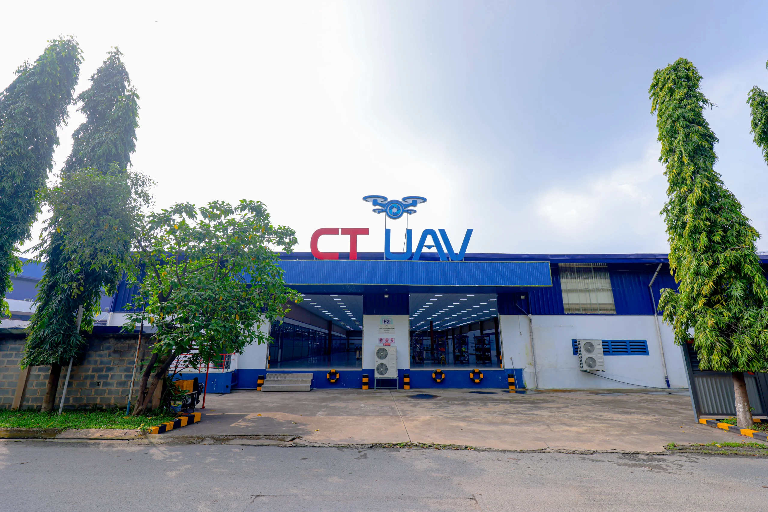
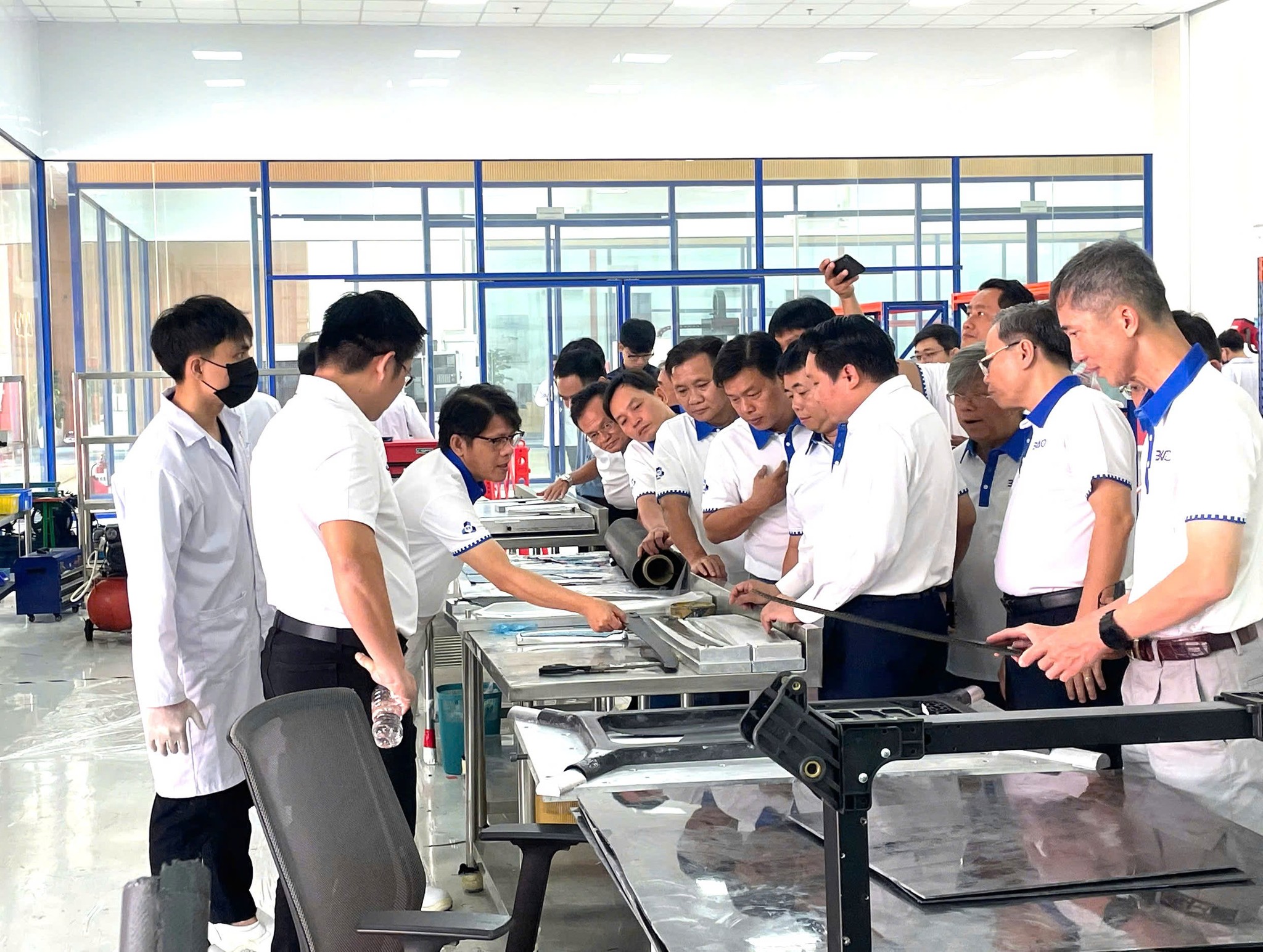
Manufacturing spaces, equipment and working practices show how aircraft move from parts to completed systems.
FROM FACTORY TO FIELD
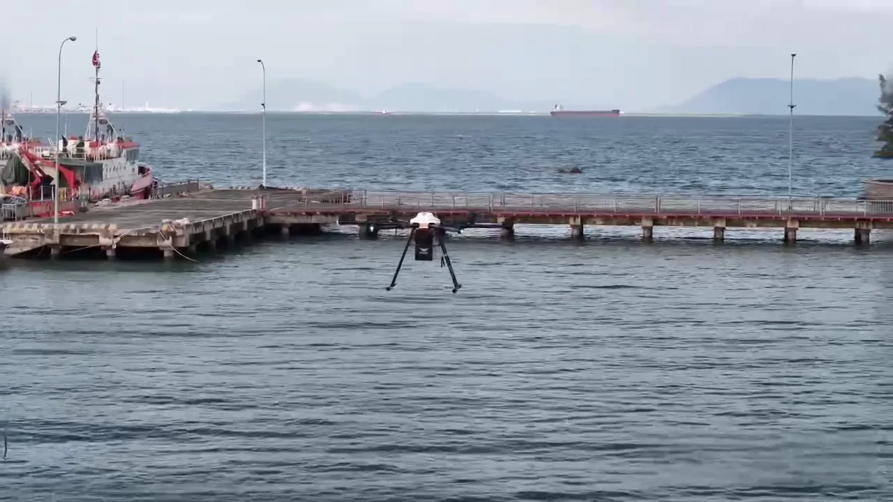
Completed aircraft move from production checks to field evaluation. Results are recorded and returned to the engineering team.